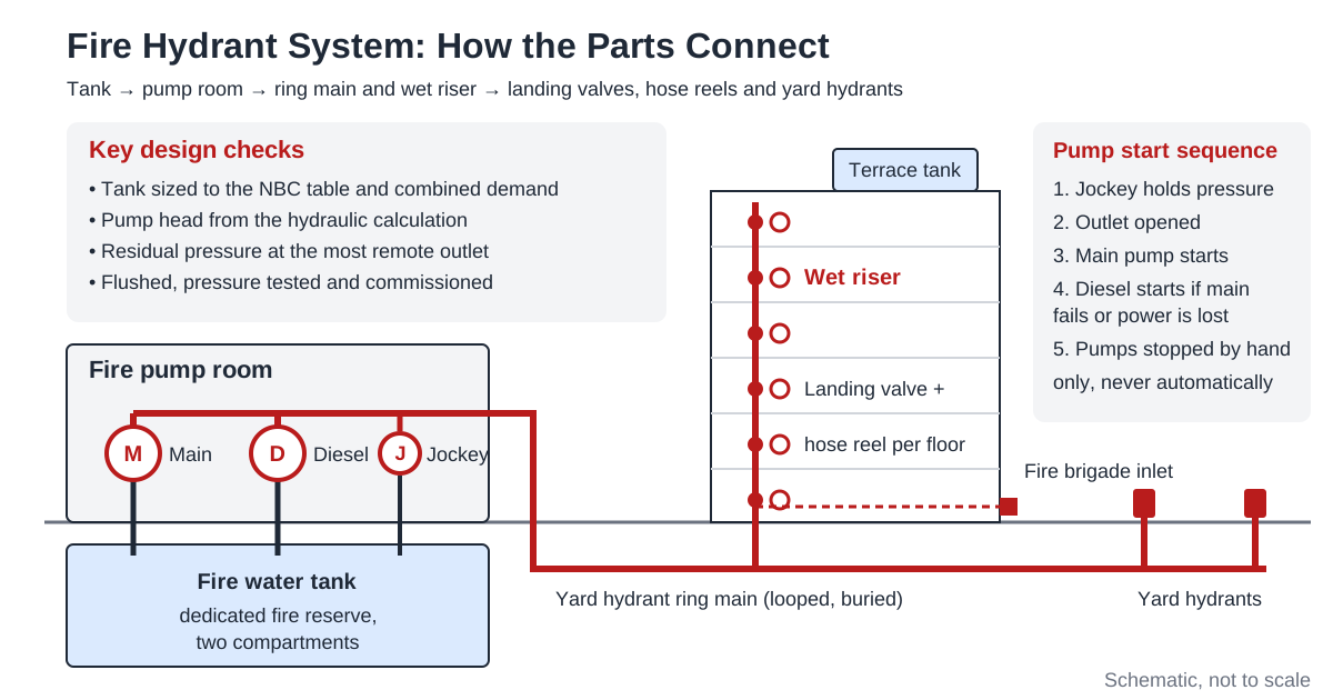
Quick answer: A fire hydrant system is a fixed network of pipes, pumps, valves and outlets that delivers water at pressure to fire fighters and trained occupants anywhere in and around a building. It has four working parts: a dedicated fire water tank, a pump room with a main electric pump, a diesel standby pump and a jockey pump, a pipe network (wet risers inside, a yard hydrant ring outside), and the outlets themselves (landing valves, hose reels, yard hydrants and the fire brigade inlet). Design follows Part F (Fire and Life Safety) of the National Building Construction Standards 2026 (NBCS 2026, SP 7:2026), which replaced NBC 2016 Part 4 from 30 April 2026 (state rules may still cite the 2016 edition), and Indian Standards such as IS 13039 and IS 3844, and the fire authority confirms it by inspection before the Final Fire NOC.
A fire hydrant system is the backbone of manual fire fighting in most Indian buildings above a modest size. When the fire brigade or a trained in-house team responds, they need water at the right pressure close to the fire, and that is what a hydrant system provides.
This guide is for building owners, factory managers, hospital and school administrators, builders and architects who want to understand a hydrant system before briefing a designer, checking drawings or preparing for a fire officer's inspection. Where a number depends on the occupancy, height or edition of a standard, we say so rather than quote a figure that may not apply to your building.
If you already know your building needs a hydrant system and want it designed and installed, our fire hydrant system installation page explains how we take a project from drawings to commissioning. If you are still working out which systems your building needs, start with our guide to fire safety requirements by building type.
What Is a Fire Hydrant System?
A fire hydrant system is a permanently installed, pressurised water network reserved for fire fighting. It is kept full and under pressure at all times, has dedicated water storage that daily use cannot draw down, and has its own pumps with backup power. When any outlet is opened, pressure drops, the pumps start automatically, and water flows at a design rate for a design duration.
"Hydrant system" covers several related parts:
- Wet riser system: a vertical pipe inside the building, kept charged, with a landing valve and hose reel at each floor.
- Downcomer: a vertical pipe fed by gravity from a terrace tank, used in some mid-rise buildings.
- Dry riser: a pipe kept empty until the fire brigade charges it from its tender; now uncommon in new Indian buildings.
- Yard hydrant system: an external ring main with hydrant outlets, used to fight fires from outside and protect open storage.
- Hose reel system: small-bore hose on the network for first-aid fire fighting by occupants.
A large building or factory often combines all of these, fed from one pump room and one fire water tank.
Why It Matters for Your Fire NOC
For most buildings that need a fire hydrant system under the National Building Code, the fire authority will not issue a Final Fire NOC until the system is installed, tested and demonstrated during inspection. At the provisional stage, the hydrant layout, tank capacity and pump room location must already appear on the fire drawings. Our guide to provisional vs final Fire NOC explains how the two stages differ, and the Fire NOC documents checklist lists the drawings a hydrant design must feed into.
Where Is a Fire Hydrant System Required?
The requirement comes from Part F (Fire and Life Safety) of the NBCS 2026, or from NBC 2016 Part 4 where state rules still cite the older edition. The code groups buildings into occupancy classes, from Group A (residential) through educational, institutional, assembly, business, mercantile, industrial and storage, to Group J (hazardous). For each occupancy and height band, the code's table of minimum fire-fighting installations by occupancy and height (Table 7 in NBC 2016 Part 4) sets out which fire-fighting installations are required: extinguishers, hose reels, wet riser, downcomer, yard hydrant, sprinklers, detection and alarm, and the water storage and pump capacity that go with them.
State rules add to NBC. In Madhya Pradesh, fire requirements sit in the Madhya Pradesh Bhumi Vikas Rules, 2012 (as amended) read with NBC, and the municipal fire department applies them when it scrutinises plans. High-rise buildings (15 m or more under NBC) almost always need a wet riser or downcomer and hose reels, and large hospitals, schools, malls and factories may need hydrants even below 15 m. Because thresholds depend on occupancy, height, floor area and current amendments, we confirm them per building. The table gives the general shape.
| Building situation | Typical hydrant provisions | Notes |
|---|---|---|
| Low-rise residential, small floor plates | Often extinguishers only; hose reels in some cases | Confirm with NBCS 2026 Part F and local bye-laws |
| Mid-rise residential or business, below 15 m | Hose reels; downcomer or wet riser depending on height and area | Terrace tank may feed a downcomer |
| High-rise residential, 15 m and above | Wet riser or downcomer, hose reels, often yard hydrants | Pump room and underground tank usually required |
| Hospitals, schools, assembly | Hose reels, wet riser, yard hydrants for larger sites | Institutional buildings are scrutinised closely |
| Factories and warehouses | Yard hydrant ring, internal hydrants, hose reels | Hazard class drives flow and storage |
| Hazardous occupancies | Full hydrant system with higher pump capacity and storage | Often combined with deluge or foam systems |
The occupancy groups and how each one is treated are covered in detail in our fire safety requirements by building type guide, so here we focus on how the system itself is designed.
Hydrant System Components Explained
A fire hydrant system is only as reliable as its weakest component. The table lists the main hydrant system components, what each does, and the Indian Standard most often cited for it.
| Component | What it does | Standard commonly cited |
|---|---|---|
| Fire water tank | Dedicated storage reserved for fire fighting | NBCS 2026 Part F for capacity |
| Main electric fire pump | Delivers the design flow and pressure | NBCS 2026 Part F; pump to relevant IS |
| Diesel standby pump | Same duty as the main pump when power fails | NBCS 2026 Part F |
| Jockey pump | Keeps the system pressurised against small leaks | NBCS 2026 Part F |
| Pressure switches and controller | Start pumps automatically in sequence | Panel to relevant IS and IEC practice |
| Ring main and risers | Carry water to every outlet | IS 13039 (external), IS 3844 (internal) |
| Landing valves | Hose connection points on each floor | IS 5290 |
| Hose reels | First-aid hose for occupants | IS 884 |
| Delivery hose and branch pipes | Carried by fire teams to connect to valves | IS 636 for hose |
| Yard hydrants | External outlets on the ring main | IS 908 (stand post type) |
| Fire brigade inlet | Lets the brigade pump into the system | NBCS 2026 Part F |
| Isolation, non-return and air release valves | Control, protect and maintain the network | Relevant IS |
Fire Water Tank
The fire water tank is usually an underground reinforced concrete tank, sometimes supplemented by a terrace tank in taller buildings. It must be reserved for fire fighting. Where a common tank is shared with domestic use, the domestic draw-off is taken from a level above the fire reserve so that daily consumption can never eat into it. Tanks are normally built in two interconnected compartments so that one can be cleaned while the other stays in service.
Risers and Ring Main
Inside the building, vertical wet risers run through protected shafts or staircases with a landing valve at each floor. Outside, a yard hydrant ring main loops around the building or plant so that water can reach any hydrant from two directions. A loop is preferred over a dead-end branch because a single break or closed valve does not cut off supply to the whole system.
Outlets
Landing valves are the hose connection points on each floor, usually located in or near the staircase lobby so fire fighters can connect from a protected position. Hose reels are mounted in the same cabinet or nearby so occupants can attack a small fire immediately. Yard hydrants are spaced around the ring main with hose boxes nearby. A fire brigade inlet at ground level allows the brigade to pump water into the system if the building pumps fail or more water is needed.
Fire Pump Room: Main, Diesel and Jockey Pumps
The fire pump room is the heart of the system. Most NBC-based designs use three pumps, each with a distinct job.
Main Electric Fire Pump
The main pump is an electrically driven centrifugal pump sized to deliver the design flow and pressure at the hydraulically most remote outlet. It starts automatically on falling pressure and, once started, runs until stopped manually. It needs a dedicated feeder that stays live when the rest of the building is isolated.
In Indian practice, pump capacity is selected from the NBC table for the occupancy and height. Values of around 2,280 litres per minute for many high-rise buildings, and around 2,850 litres per minute for more demanding occupancies, appear widely in NBC-based designs, but the correct value for your building must be read from the current NBC table and confirmed against the hydraulic calculation. Pump head is not a fixed figure: it is calculated from the height of the building, the friction loss through the pipework and fittings, and the residual pressure needed at the most remote outlet.
Diesel Standby Pump
The diesel pump has the same duty (flow and head) as the main electric pump and starts automatically if the electric pump fails or mains power is lost. It needs a fuel tank sized for the required running period, starting batteries with a charger (commonly two sets), cooling, an exhaust led safely outside, and a controller that attempts a set number of cranking cycles before signalling failure. Most authorities in India expect a diesel pump, so we treat it as the default; alternatives need the authority's acceptance.
Jockey Pump
The jockey pump is a small pump that keeps the network topped up and pressurised. Every pipe network leaks slightly at joints and valves. Without a jockey pump, those small pressure drops would start the main pump repeatedly. The jockey pump starts at a pressure slightly above the main pump's start setting and stops once pressure recovers, so the main pump only starts when there is a genuine flow demand. A jockey capacity of around 180 litres per minute is commonly specified in NBC-based designs, with its head set slightly above the main pump's.
Pump Start Sequence
Pressure switches on the delivery header are set in a staggered sequence (set points depend on system pressure):
- The jockey pump holds normal standing pressure, starting and stopping to make up small leaks.
- An outlet is opened; pressure falls faster than the jockey pump can make up.
- At the main pump's set point, the electric pump starts.
- If it fails or power is lost, pressure keeps falling to the diesel pump's set point, and the diesel pump starts.
- Main and diesel pumps run until stopped manually after the fire is out.
The panel should show pump running, pump failure, power available, low fuel and battery status, and these signals should be repeated to the fire control room or security cabin where one exists.
Pump Room Checklist
- Location with direct access, ideally at ground level or the first basement, and close to the fire water tank.
- Flooded suction (pumps below tank water level) wherever possible, so pumps do not depend on priming.
- Separate suction for each main pump, with isolating valves and strainers.
- Delivery header with non-return valves, isolating valves, pressure gauges and a test line.
- Pressure switches for each pump, tested and labelled.
- Diesel engine fuel tank, exhaust, ventilation and battery charging.
- Fire-resisting enclosure, drainage, lighting and emergency lighting.
- A schematic drawing and operating instructions displayed on the wall.
Fire Water Tank Capacity and Water Storage
Fire water tank capacity is one of the questions clients ask first, and one where a quoted number is most likely to be wrong for a specific building. The right answer depends on what the building needs to supply and for how long.
How Storage Is Decided
NBCS 2026 Part F sets the minimum underground and terrace storage for each occupancy and height band in its fire-fighting installations table. On top of that, the designer checks:
- Which systems draw from the tank. If sprinklers share the tank, storage must cover both demands for the required duration (see our fire sprinkler system design guide).
- The design flow and duration. In its simplest form, storage equals design flow multiplied by the required running time, then rounded up to the code minimum or above.
- Reliable inflow during a fire. Some authorities allow credit for a dependable incoming supply; many do not. We design on the assumption that there is no inflow unless the authority confirms otherwise.
- Additional risk. Hazardous storage, tank farms, or insurer requirements (for example, insurance-led standards such as the former TAC rules) can push storage well above the NBC minimum.
Underground Tank Versus Terrace Tank
| Feature | Underground static tank | Terrace tank |
|---|---|---|
| Main purpose | Primary fire reserve feeding the pump room | Gravity supply to downcomers and a first-aid reserve in tall buildings |
| Typical location | Below ground, near the pump room | On the terrace, above the risers |
| Fed by | Municipal or borewell supply | Transfer pumps from below |
| Reliance on pumps | Yes, needs the fire pumps | Works by gravity for upper floors |
| Key checks | Compartments, fire brigade suction access, overflow, level indicator | Structural load, connection to risers, non-return arrangement |
Tank Design Points
- Build as two interconnected compartments with a common sump so the tank can be cleaned in halves.
- Provide a water level indicator readable from the pump room.
- Provide an access point where the fire brigade can draw water directly with its own tender.
- Make sure domestic draw-off sits above the fire reserve level if the tank is shared.
- Keep the tank structurally sound and watertight; leaks often go unnoticed until inspection.
Fire Hydrant System Design: Step by Step
Fire hydrant system design follows a predictable sequence. Skipping a step, especially the hydraulic check, is the most common reason a system fails its pressure test or the fire officer's flow demonstration.
- Classify the building. Confirm the NBC occupancy group, height, number of floors and basements, floor area and any mixed uses. This decides which hydrant provisions apply.
- Read the code table. From NBCS 2026 Part F and the state rules, list the required systems: hose reels, wet riser or downcomer, yard hydrants, sprinklers, tank storage and pump capacity.
- Fix outlet locations. Place landing valves and hose reels so every part of each floor can be reached by the hose length, normally at staircases and lobbies. Place yard hydrants around the building so no part is too far from an external outlet; IS 13039 gives spacing and distance guidance that depends on hazard.
- Route the network. Prefer loops, avoid mains under buildings, keep risers in protected shafts.
- Size the pipes. Choose diameters so friction loss at design flow leaves enough pressure at the most remote outlet.
- Run the hydraulic calculation. Calculate the pressure needed at the pump to deliver the required residual pressure at the hydraulically most remote outlet, allowing for static lift, friction and fittings. A residual pressure of around 3.5 bar at the most remote hydrant is commonly cited from IS 13039, but confirm the figure for your design standard.
- Select the pumps. Choose the main, diesel and jockey pumps for the calculated duty, and check the pump curve so the pump is not overpressurising lower floors. Pressure-reducing arrangements may be needed on lower floors of tall buildings.
- Size the tank. Confirm storage against the code table and the combined demand of all systems sharing it.
- Detail the pump room. Prepare the pump room layout, the suction and delivery arrangement, the control logic, and the fuel, exhaust and ventilation.
- Prepare drawings and documents. Produce the fire-fighting layout, riser diagram, pump room layout, hydraulic calculation and equipment schedule for submission with the Fire NOC application.
Pipe Material and Protection
Above-ground mains are commonly heavy-class mild steel with welded or grooved joints, painted red. Buried mains need corrosion protection such as wrapping and coating, and supports and thrust blocks must resist the forces when a pump starts or a valve closes quickly.
Wet Riser System Design Details
A wet riser system is the internal part of the hydrant network. It brings water up through the building so fire fighters do not have to drag hose up the stairs from the street.
Riser Location and Outlets
- Locate risers within or adjacent to protected staircases or fire-fighting shafts, so fire fighters connect from a protected area.
- Provide a landing valve at each floor, including basements, with a hose cabinet holding delivery hose and a branch pipe.
- Provide a hose reel on each floor, drawn from the riser, so occupants can tackle a small fire.
- Provide an air release valve at the top of the riser and a drain valve at the bottom.
- Provide a fire brigade inlet at ground level connected to the riser, with a non-return valve.
Pressure on Lower Floors
In tall buildings, a pump sized to deliver enough pressure at the top floor can produce too much pressure at the bottom. Excess pressure makes hoses hard to control and can damage equipment. Designers deal with this by zoning the building into pressure zones, by using pressure-reducing landing valves on lower floors, or by a combination. The approach must be shown in the riser diagram so the fire officer can see how pressure is managed.
Yard Hydrant System Design Details
A yard hydrant system protects the building from outside and is especially important for factories, warehouses, tank farms, hospitals with large campuses and any site with open storage.
- Ring main: a closed loop with sectional isolating valves, so a damaged length can be isolated without cutting off the ring.
- Spacing: set by hazard; IS 13039 gives guidance, with closer spacing for higher hazards.
- Distance from walls: far enough to protect crews from collapse and radiant heat, close enough for hose to reach.
- Hose boxes and access: hose boxes beside hydrants, all on or near the fire tender road and kept clear of vehicles and stored goods.
- Monitors: in high-hazard areas, fixed water monitors throw a large jet without a crew holding a hose.
Industrial sites in Pithampur, Dewas and Indore often have yard rings that grew piecemeal as sheds were added. A common finding in our fire safety audits (see the audit checklist) is a ring turned into dead-ends by a valve closed during an extension and never reopened.
Worked Example: Hydrant Design for a Mid-Rise Hospital
The example below is illustrative only. It shows how the design steps fit together; it is not a design for any real building, and the numbers are chosen to explain the method, not to state code values for your project.
Building (illustrative): a hospital in Indore, ground plus six floors, about 24 m high, one basement, with a separate service block.
- Classification: institutional occupancy above 15 m, so high-rise under NBC. The designer reads the NBC table for this group and height, and the Madhya Pradesh rules.
- Systems (illustrative): hose reels and wet risers on every floor including the basement, yard hydrants, sprinklers, detection and alarm.
- Outlets: two staircases, so two wet risers with a landing valve and hose reel at every floor; yard hydrants on the fire tender road.
- Hydraulic check (illustrative): the most remote outlet is the top-floor landing valve on the far riser. Pump head = static lift of about 24 m + friction loss through ring and riser at design flow + required residual pressure at the outlet.
- Pumps: a main electric pump and an identical diesel pump sized from the NBC table and confirmed by the calculation, plus a jockey pump.
- Lower floors: the designer checks ground-floor pressure and adds pressure-reducing valves if needed.
- Storage: the larger of the NBC minimum and the combined hydrant and sprinkler demand for the required duration, rounded up.
- Pump room: at ground level beside the tank, with flooded suction and direct access from the service road.
Each decision is traceable to a rule or a calculation, so when the fire officer asks why the pump head is what it is, the answer is on paper.
Pressure Testing, Commissioning and Handover
A hydrant system is not complete when the last pipe is fitted. It is complete when it has been flushed, pressure tested, commissioned, demonstrated to the fire authority and handed over with documents.
Hydrostatic Pressure Testing
Every section is pressure tested before it is concealed or buried, and the whole system again on completion. The test pressure is set by the design standard and specification, usually as a multiple of the maximum working pressure, and held for a specified period while joints are inspected and the gauge watched for any drop. Because figures vary by standard and by client or insurer specification, we state them in the project test procedure and record actual readings.
- Inspect: supports, joints, valve orientation and pipe identification.
- Flush: remove debris and welding slag that could jam valves or nozzles.
- Fill and vent: fill from the lowest point, venting air at high points.
- Test sections: pressurise, isolate, hold, and record start and end readings.
- Repair and retest any leaking section, then test the complete network.
- Certify: sign test certificates with dates, pressures and duration.
Commissioning the Pumps
- Check the rotation, alignment and mounting of each pump.
- Set and test the pressure switches so the jockey, main and diesel pumps start in the correct sequence.
- Simulate a power failure to prove the diesel pump starts automatically.
- Run the diesel engine for a period and check fuel, cooling, exhaust and battery charging.
- Run a flow test through the test line and record flow and pressure against the pump curve.
- Confirm all alarms and status signals reach the panel and any remote monitoring point.
Flow and Pressure Demonstration
At the most remote landing valve and yard hydrant, connect hose and branch pipe, open the valve and measure residual pressure while flowing. This is the test the fire officer is most likely to ask to see during inspection for the Final Fire NOC.
Handover Documents
- As-built drawings of the network, risers and pump room.
- Hydraulic calculation and pump selection.
- Pressure test certificates.
- Pump test records and manufacturer test certificates.
- Equipment schedule with makes, models and standards.
- Operation and maintenance manual and a pump start sequence chart.
- A training record for the building's staff.
What the Fire Officer Checks During Inspection
Expect the fire officer to walk the building and pump room and ask for a demonstration. Common checks include:
- Tank capacity and level indicator, and whether the fire reserve is protected from domestic use.
- Pump room access, condition, and that all three pumps start automatically.
- Diesel pump starting on simulated power failure, and fuel level.
- Pressure at the most remote landing valve and hydrant while flowing.
- Hose reels, landing valves and hose cabinets complete with hose and branch pipes.
- Yard hydrants accessible, painted, and with hose boxes.
- Fire brigade inlet accessible and labelled.
- Signage, pipe colour, and that valves are locked or strapped in the correct position.
- Documents: drawings, test certificates and maintenance arrangements.
For the full inspection process in Madhya Pradesh, see our guide on how to get a Fire NOC in Indore and Madhya Pradesh.
Maintenance and Routine Testing
A hydrant system that is not maintained will fail when it is needed. Routine checks keep it ready, and records prove to the fire authority at renewal that it has been kept ready.
| Frequency | Typical checks |
|---|---|
| Daily or weekly | Pump panel status, system pressure, diesel fuel level, battery condition, tank level |
| Weekly | Run the diesel pump for a short period; check for leaks in the pump room |
| Monthly | Run the main electric pump; inspect hose reels and landing valves; check cabinets are complete |
| Quarterly | Operate a sample of yard hydrants and landing valves; check pressure switch settings |
| Half-yearly or annually | Full flow test; service the diesel engine; inspect and test hoses; clean tank compartments in turn |
| After any modification | Retest affected sections; update drawings |
Frequencies here are typical practice; follow the manufacturer's manual, the relevant Indian Standard and any insurer requirement for your site. An annual maintenance contract for fire systems is the simplest way to make sure these checks happen and are recorded.
How DSTechnoverse Helps
DSTechnoverse designs, supplies, installs, tests and commissions fire hydrant systems across Indore, Pithampur, Dewas, Ujjain, Bhopal and the rest of Madhya Pradesh. Every project is led by Mohit Malviya, our accredited fire engineer, from the code check and hydraulic calculation through to the pump room, pressure testing and the fire officer's inspection. We can take on the complete fire hydrant system installation, integrate it with sprinklers and alarms under our wider fire fighting system installation service, and support your Fire NOC application. Contact us with your drawings for a scoped proposal.
Frequently Asked Questions
What is a fire hydrant system?
A fire hydrant system is a fixed, pressurised pipe network with its own water storage and pumps, reserved for fighting fires. It supplies water to landing valves and hose reels inside the building and to yard hydrants outside, so that fire fighters and trained occupants can connect hoses close to the fire. It starts automatically when an outlet is opened and keeps running until stopped manually.
What is the difference between a wet riser and a fire hydrant system?
A wet riser is one part of a fire hydrant system. It is the vertical pipe inside the building that carries water to a landing valve and hose reel on each floor. The complete hydrant system also includes the fire water tank, the pump room, the external yard hydrant ring, the fire brigade inlet and the controls that make everything work together.
Why does a hydrant system need three pumps?
Each pump has a separate job. The main electric pump delivers the design flow. The diesel pump has the same duty and takes over if the electric pump fails or power is lost. The jockey pump is small and keeps the network pressurised against minor leaks, so the main pump only starts when there is genuine demand from an open outlet.
How is fire water tank capacity decided?
Capacity starts from the minimum set in the NBCS 2026 Part F table for the building's occupancy and height. The designer then checks the combined demand of all systems drawing from the tank, such as hydrants and sprinklers, for the required duration, and any insurer or local requirement. The larger figure governs. Because these inputs differ for every building, capacity should be confirmed per project.
Where should the fire pump room be located?
The pump room should be close to the fire water tank, with direct access for the fire brigade, ideally at ground level or the first basement. It should be enclosed in fire-resisting construction, ventilated for the diesel engine, drained and lit with emergency lighting. Pumps should have flooded suction wherever possible so they do not depend on priming.
How is a fire hydrant system pressure tested?
Each section is filled, vented and pressurised with a test pump to the pressure set in the design specification, usually a multiple of the working pressure. The pressure is held for a specified period while joints are inspected and the gauge is watched for any drop. Leaks are repaired and retested, then the complete system is tested and certificates are signed.
Can the fire water tank be shared with domestic water?
It can be shared only if the fire reserve is protected. The domestic draw-off must be taken from a level above the fire reserve, so that daily use can never reduce the water held for fire fighting. Many designers and authorities prefer a fully separate fire tank. Either way, the arrangement must be shown clearly on the drawings submitted for the Fire NOC.
How often should a hydrant system be tested?
Pump panel status and system pressure should be checked daily or weekly, the diesel pump run weekly, the electric pump run monthly, and outlets operated in rotation. A full flow test and diesel engine service are usually done annually. Follow the manufacturer's manual and relevant Indian Standard, and record every test, because the fire authority may ask for records at renewal.
Need a Fire NOC or a fire safety installation? DSTechnoverse handles provisional and final Fire NOC applications and renewals, and designs, supplies, installs and commissions fire fighting systems: hydrants, sprinklers, fire alarms, extinguishers and suppression systems. Work is led by Mohit Malviya, our accredited fire engineer, from our base in Indore, Madhya Pradesh. Talk to our team.
Related services
Related articles
- Fire Safety Requirements for Buildings: NBC Occupancy Groups, Height and Systems by Building Type
- Fire Sprinkler System Design: Types, Hazard Classes, Heads and Testing
- Provisional vs Final Fire NOC: What Each Covers and When You Need It
- Documents Required for Fire NOC: Complete Checklist by Stage and Building Type